Chemical Process Safety (PSM/RMP)
The following incident is a precautionary example of the potential hazards of improperly depressurizing piping to remove a hydrate. During production operations, a control room operator observed a decrease in gas lift pressure supplied through a pipeline to a remote well location. The control room operator notified the onboard platform operators of the pressure drop and the possibility of a hydrate forming inside the 3-inch gas lift piping. The control room operator and platform operators planned to isolate and bleed the pressure to remove the possible hydrate. The control room operator from his station closed the pipeline shutdown valve (SDV) upstream of the manual flow control valve. Additionally, the platform operators physically closed the manual isolation valve upstream of the SDV, assumed the hydrate location, and departed the pipeline. The platform operators then started to relieve the pressure downstream of the hydrate location to atmospheric pressure without properly isolating the pipeline from the bleed point through a ball valve assembly attached to the 3-inch gas lift piping. The ball valve assembly consisted of a threadolet, threaded steel pipe nipples, two 1-inch ball valves inline, and a 90-degree elbow that pointed upward. With approximately 900 psi trapped behind the valve, the assembly separated from the threadless, striking one of the platform operators under the left armpit area, and causing bruising and swelling. The injured offshore worker was sent for medical treatment and was later released to full duty. The valve assembly could not be found and is suspected to have fallen overboard after striking the worker. Read more ... Add new comment
The Emergency Planning and Community Right-to-Know Act (EPCRA) requires businesses that store and/or manufacture, process, or use certain chemicals to complete the Tier II (EPCRA 311 and 312) Report and/or the Toxics Release Inventory (EPCRA 313) Report, also called the Form R. Section 112(r) of the Clean Air Act focuses on risk management for accident prevention. While these three (3) programs have similar reporting elements, they have significant differences outlined in the following table.
And I will bet someone will suggest a closed-top/bung-style container. Keep in mind that this is NOT preventing the event/failure that makes a bung top drum a safety device, but it could be a protection layer and most certainly would be considered a mitigation layer should we have an eruption from the container. When using the bung style drum, remember to ALWAYS have it vented so as to not "launch" the drum, making it a hazard. We always used the 2" bung for our hose/sparger and the 0.5" bung for our "vent". These bung drums also slow the liberation of gas/vapors from our absorbent material (usually water or caustic). So give it some consideration; it may just be the ticket for those unexpected "surges" caused by improper energy isolation or blockage breaking free in the piping. The same application is used for 5-gallon containers such as "draining oil" from a refrigeration "oil pot" where sputtering is not uncommon. But remember, VENTING is critically important. We can lay a rag over the vent to reduce splash/sputter from the opening; it can also help reduce odors and off-gassing - BUT NEVER BLOCK the vent with any mechanical device or leave it plugged/closed.
Person 1 shut off the air and nitrogen gas supplies before yelling to the workshop to call the HSE leader (nurse). Person 2, who was holding the cylinder, suffered severe injuries to his legs and one hand. Person 3 was injured when the booster pump collided with his legs, probably after parts of the cylinder had hit it. Both the injured people were quickly taken care of by the nurse and other response personnel, first at the incident site and then in the Heimdal
The direct cause of the incident was that the nitrogen gas cylinder burst during pressurization because it was probably exposed to a pressure significantly above its design level.
The investigation has found that the direct cause of the leak was corrosion under the insulation in a 4" pipe for heavy naphtha from the distillation tower. The lack of inspection and repair meant that the corrosion had continued long enough for a hole to form in the pipe. Piping and equipment in a refinery can be exposed to external and internal corrosion. To monitor and repair such damage, they are inspected at specified intervals. The pipe where the leak occurred had been removed from the maintenance program by mistake in 2008. This error was discovered in 2013, but instead of being restored to the program, the pipe continued to be let out of the equipment strategy. This pipe was accordingly last inspected for corrosion under its insulation in 2004.
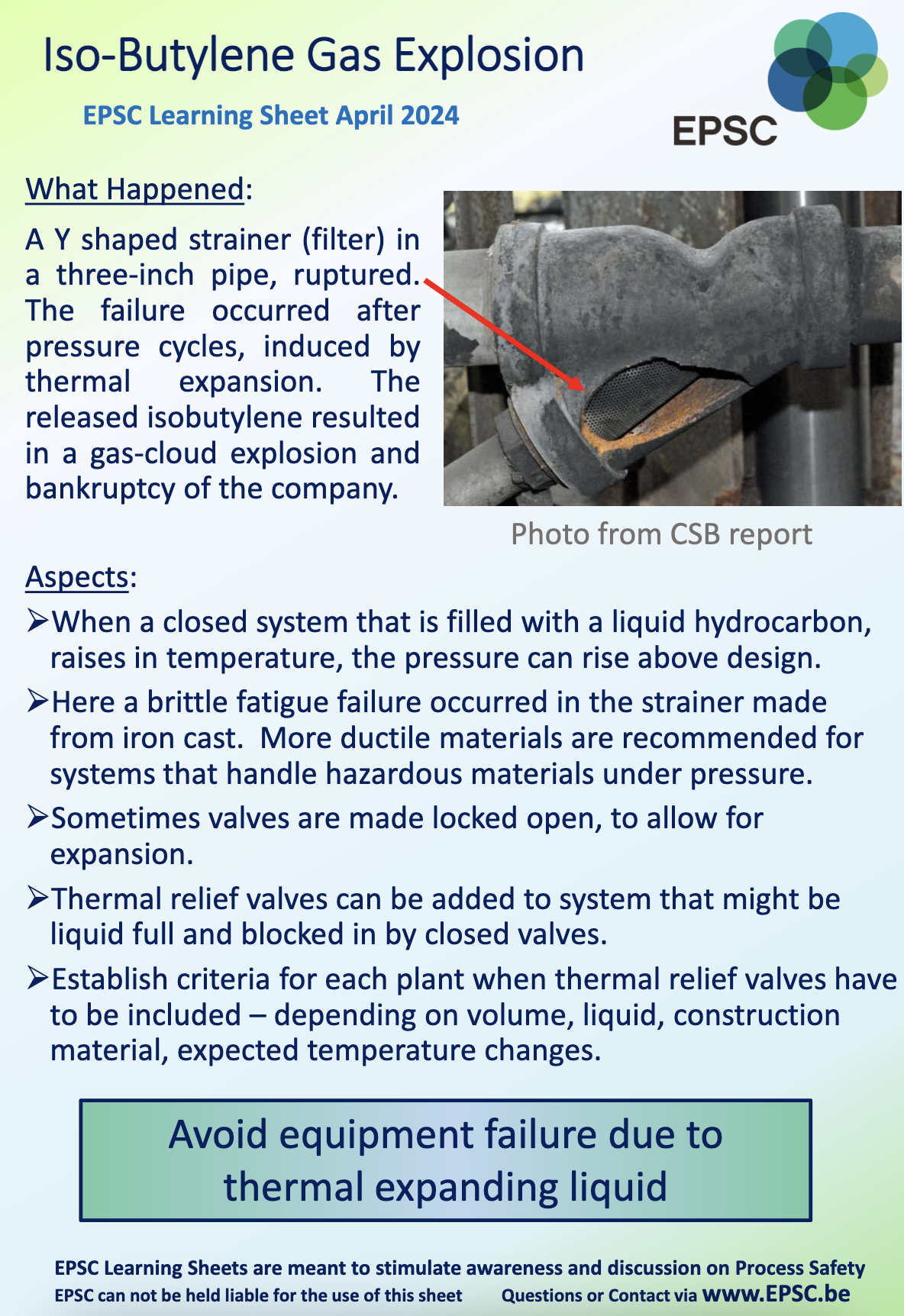
Aspects:
|
Partner Organizations I am proud to announce that The Chlorine Institute and SAFTENG have extended our"Partners in Safety" agreement for another year (2024) CI Members, send me an e-mail to request your FREE SAFTENG membership
Member Associations
|
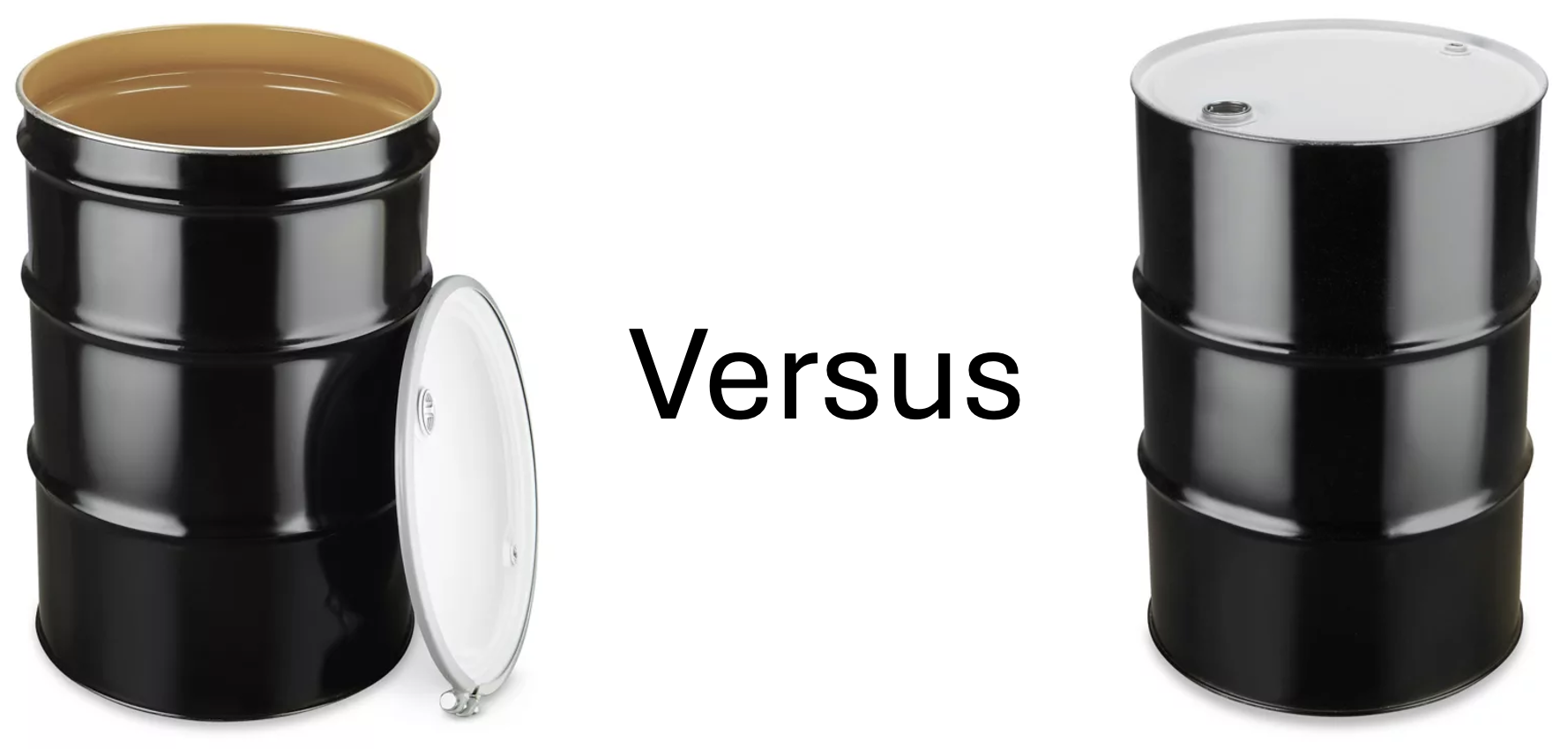 I have written many articles discussing evacuating hazardous materials from a piping system. Over my career, I learned that using an open-top container can have disastrous results. It may sound silly or petty, but when something fails in the tasks and the hazardous material erupts from the open-top container, making contact with the worker(s), you will begin to ask... is there a better way?
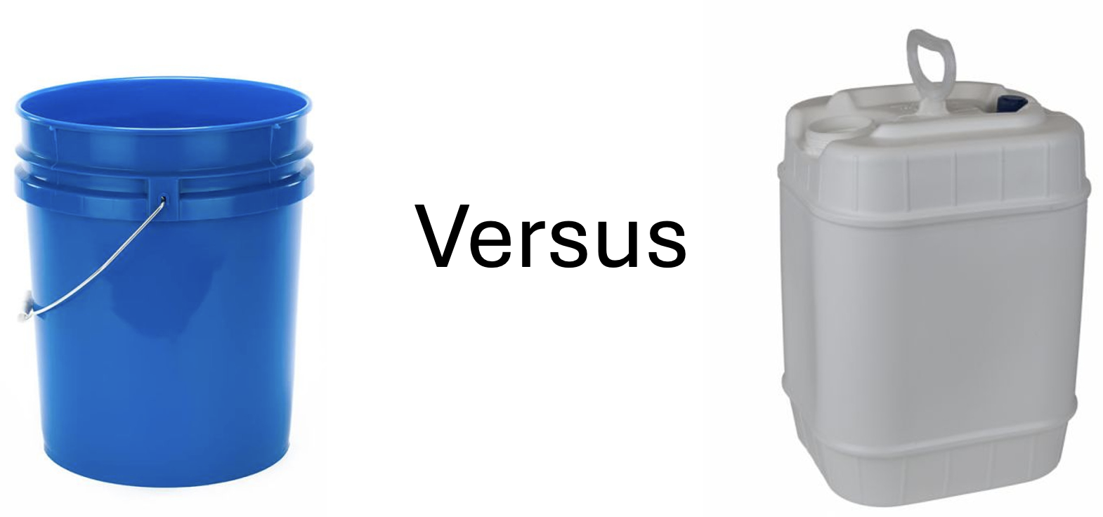
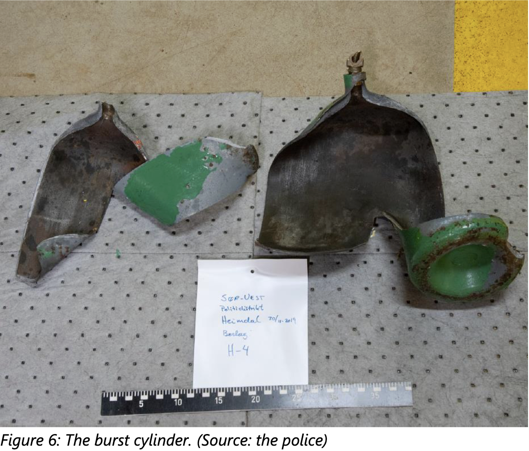 Two people were severely injured after a Nitrogen cylinder catastrophically failed during refilling/pressurization.